Automated Execution of Multiple KNIME Workflows
When using the open source KNIME Analytics Platform to build sophisticated data processing and analysis pipelines, I often find myself building workflows that consist of so many nodes they become difficult to manage. This complexity can be managed by grouping nodes into processing stages and then bundling those stages into meta-nodes so that the overall workflow layout is easier to follow.
However, I’ve found that this approach still leaves workflows unwieldy to work with as you still have to open the meta-nodes to explore and troubleshoot their processing. Over the years I’ve worked with KNIME, I’ve developed a habit of breaking larger workflows up into smaller individual workflows representing each processing stage in the overall pipeline. This serves to make building and debugging each processing step much more tractable at the cost of requiring more storage for persisting the outputs of one stage so that they may be used as the inputs of the next stage.
Another small drawback of separate workflows is that they all need to be executed in order for the overall pipeline to complete. But, by following a basic workflow naming convention, you can build a control workflow in KNIME to run each step’s workflow in order and monitor their results. In this blog posting, I’m going show the technique as applied to the following two-level collection of workflows:
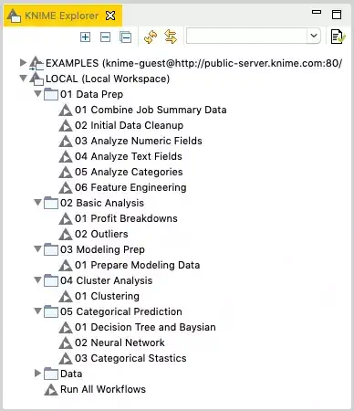
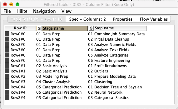
You’ll notice in this example that there are five top level workflow groups representing the stages of processing. Each workflow group then contains one or more workflows representing a processing step for its stage. This is where the workflow naming convention comes into play: I assign each workflow stage a two-digit number at the start of its name which represents its position in the execution sequence. I then do the same thing for each workflow inside of a given stage so that a given stage’s steps may also be run in order. Note that the step number is zero padded to keep it fixed to exactly two digits. This limits the workflow runner to 99 stages and 99 steps, but this technique can be extended to more digits should the need arise.
The single workflow at the workspace root is not numbered and is titled Run All Workflows. This is the control workflow that is responsible for running all the other workflows in the correct order. You can create any number of stage and nested step directories in your workspace to test with (as long as you follow the numbering convention mentioned previously.)
The master workflow starts with some basic steps to just list the top-level files in the workspace and extract the path information for just the ones that represent stages:
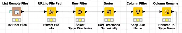
The first node lists the files in the workspace. The key here is to use the appropriate KNIME URI prefix to provide a relative reference the workspace so that file list is not dependent on a fixed path on the current machine. In this case, we use the knime://knime.workflow prefix with a parent directory reference so that the file lister ascends to the root of the workspace.
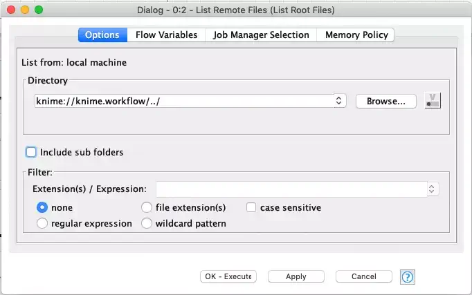
The List Remote Files node will return all files and subdirectories in the workspace directory as URLs:
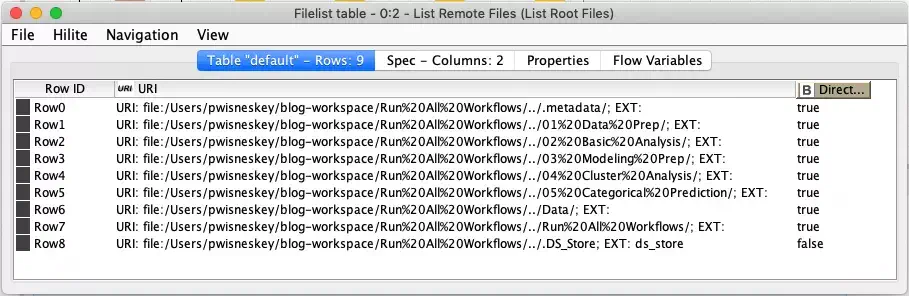
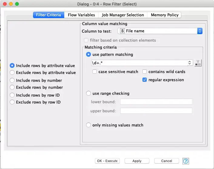
To make it easier to select only the stage directories, we use the URL to File Path node to extract the various path components from each URL. The output from this node will have separate columns including just a file name column with just the file and directory names in it. We immediately filter on the file name column to select only the numbered stage directories. The applied filter is a regular expression that selects only names that start with two digits (e.g. the numbered stages).
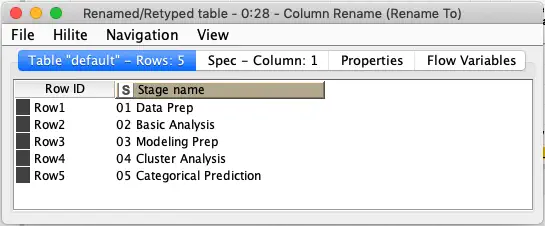
Immediately after we select the appropriate stage directory names, we sort them to ensure that they are in proper order since we should not assume the file list returns names in any particular order. We then drop all of the other columns since we are just interested in the stage names and then rename the column to make its purpose clearer:
Now that we have all of the stages, we need to get the individual steps that make up each stage. We do this by looping over the stages and listing each stage’s directory the same way we did previously.
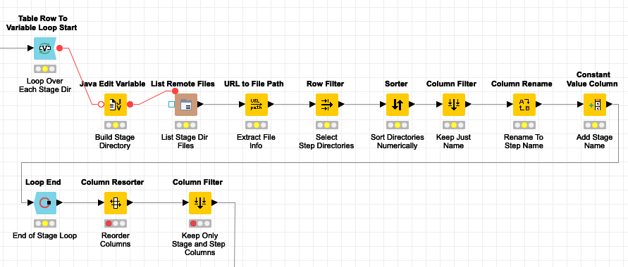
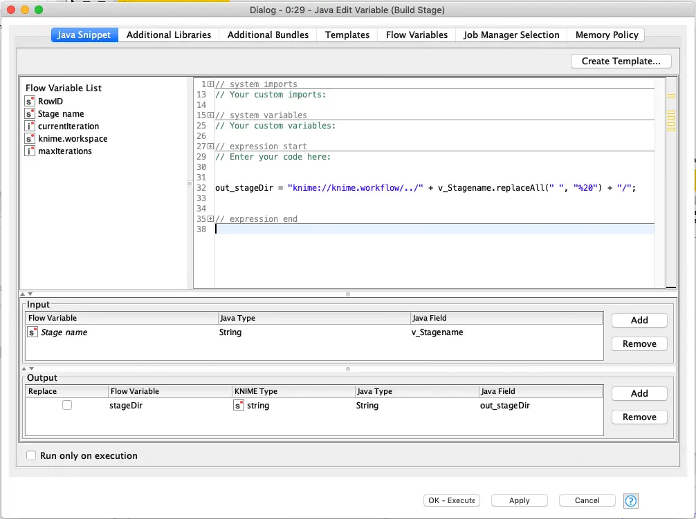
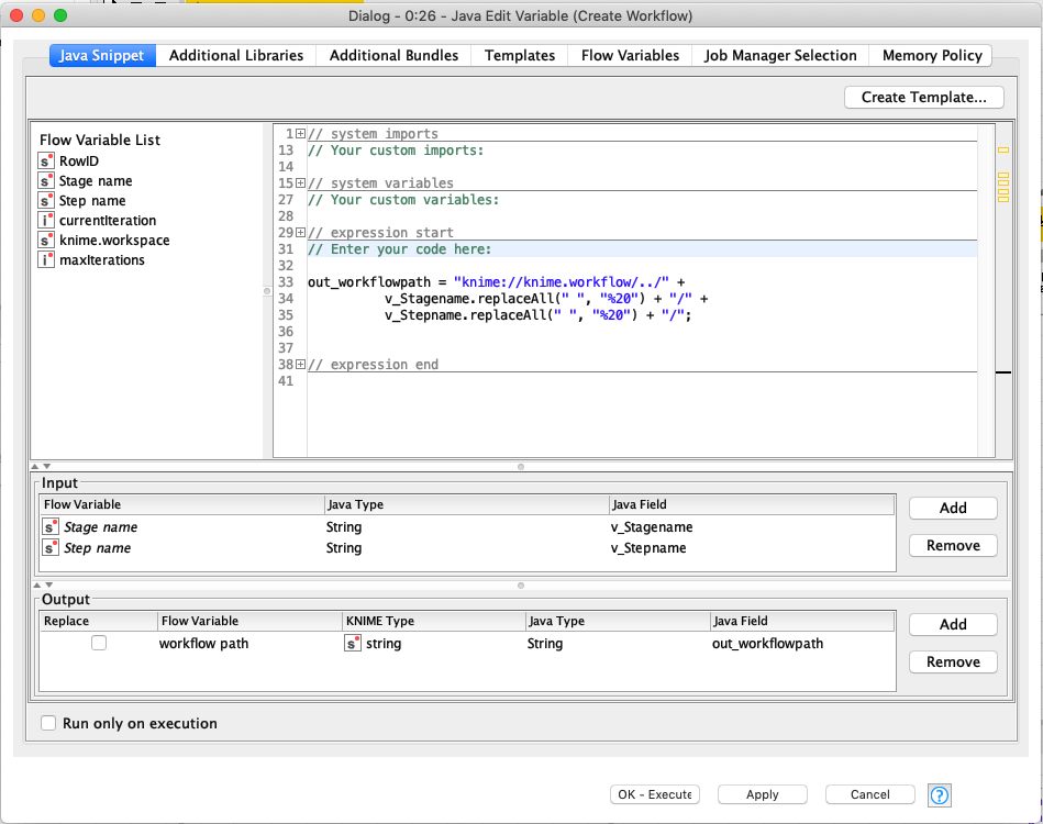
The key difference for listing the steps is that we must construct the URL to the stage directory we want to list the steps for. This is done in the Java Edit Variable node based on the stage name variable that is set for each loop iteration. As with the initial directory listing, we take care to reference the directory path with a relative link. Also, since we are creating a URL we need to replace any spaces with their URL encoded equivalent:
The remaining processing nodes work the same as the stage listing nodes: they extract only the step names, sort them, rename them, and then insert the stage name as a column in the results. Once we’ve looped over all stages, we then clean up the resulting table to keep just the stage and step name columns:
At this point we have an ordered list of all stages and steps that must be executed to complete the processing pipeline. This is done with a final loop to execute one step at a time:
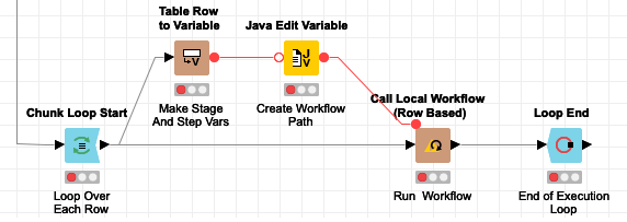
As with listing the step directories, we need to create a flow variable with the relative path to the workflow to be executed:
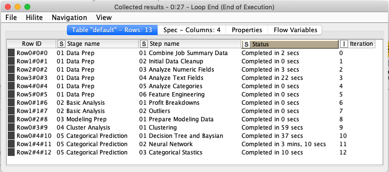
The step’s workflow is executed with the Call Local Workflow (Row Based) node which is configured to use the workflow path flow variable for which workflow should be run. The step’s row is used as the input to the workflow, but it is ignored by the embedded workflow and the row is output from the run workflow node but with an additional column that contains timing information for the step’s workflow that was executed. At the end of the loop, all of the steps’ result rows are accumulated together and produce a summary of the entire pipeline’s execution:
There are two caveats to this technique:
- All step workflows need to be saved in a reset state. If any of their nodes are saved in an executed state, those nodes will not be executed by the call workflow node, but all remaining nodes will be executed. The final execution state of the workflow is not saved by the call workflow node so there is no need to reset the state between runs.
- If any of the embedded workflows contain nodes that are not connected to the actual workflow execution (e.g. orphan nodes just left in the workflow), the workflow run will be considered a failure and it will be listed as so in the status column. Also, each workflow’s output will be shown in the KNIME console so progress can be monitored during the runs.
This technique of using the Call Local Workflow node is a very powerful one and can be leveraged in many other ways. For example, a source file that just lists the names or paths of workflows to be executed could also be used instead of relying on a numerical file naming convention to dynamically determine what to run. In even more advanced uses, you can also leverage the container input and output nodes to pass data in and out of the executed workflows. By passing data you can then leverage embedded workflows in loops to sequentially process sets of data or even in response to external events (leveraging the streaming capabilities of KNIME.) Any way you use it, Call Local Workflow is an important part of the KNIME ecosystem and worth getting familiar with.
